
Opto-Electronic Speed
Timing
- For Control Line Speed Models -
Designed and developed by Göran Olsson, Stockholm, Sweden
First posted June 15, 2000Updated 27th May, 2007
System Overview
The system components are:
|
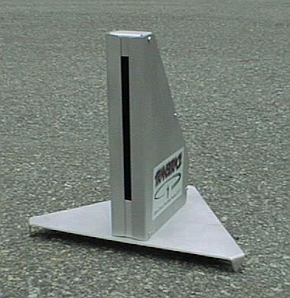 |
Sensor
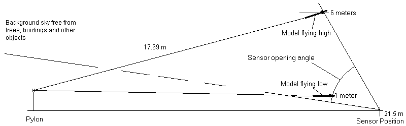
The sensor is contained in a box with a vertical slit opening on one side. It stands on a tripod. The height is 205 mm. In operation the box is placed on the ground with the slit facing the circle at a 21.5 meter radius (for the case of F2A, with 17.69 m lines). At this distance the box will stay clear of starting and landing models, but note that it will still need protection from dollies.
The sensor employs a phototransistor for detecting the passing of a model by optical means. It is mounted on a printed circuit board that also has some important signal conditioning circuitry.
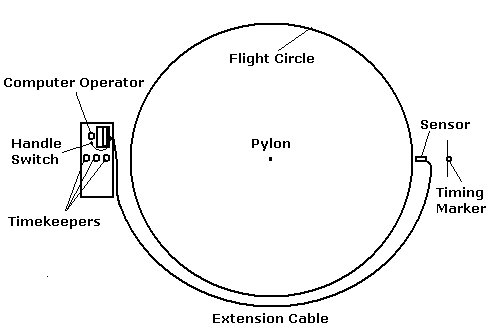
Flight Circle Layout
Top View:
Sideview Section:
Detailed Description
The phototransistor receives light from the part of the sky in view through the slit. The angle of view is from 9° to 50° vertically, relative to the horizontal, and around 4° horizontally. The phototransistor light sensitive area is circular with a diameter of around 1 mm. The distance of the phototransistor to the slit is 110 mm at the lower limit and 200 mm at the upper. The slit is covered by a blue transparent filter, to reduce the contrast between clouds and clear sky, and to reduce the sensitivity to infrared light.The unit should be aligned so that it stands horizontally, pointing towards the pylon.
When a model enters the field of view, it obscures a small part of the sky, and the phototransistor current drops momentarily by a tiny fraction. The circuitry detects this drop and outputs a signal pulse, and blinks a red light on the rear panel.
From the model dimensions, its range of flying heights, and the sensor field of view as above, the photocurrent drop can be estimated. For an F2A model it is around 0.5 %, and rather independent of the flying height: Low: Near sensor, but wing seen from oblique angle. High: Far from sensor, but wing seen at nearly right angle. To detect a current drop as small as fractions of a percent, some special techniques have to be employed to adapt to the lighting conditions and exclude light variations from other sources than the models. Think about this: The sensor must be able to detect a light change of only 0.5 %. At the same time, the brightness of the sky could vary by a factor of ten! In all a factor of 2000!
There has to be a lower limit of the field of view, as objects near the ground must not disturb. The pilot, mainly (!!) but also background trees, circle fence and so on. This leads to models passing lower than around 0.6 meters (2 ft) being missed.
Two more obvious limitations are that no direct sunlight must fall onto the phototransistor, and that the sky in view must be unobstructed. No tall trees or buildings in the rear! To block stray light, the box inside surface is covered by black velvet-like material. A minimum angle of 10° between the sun and the sensor direction is recommended. Also, the sensor should not be placed in the shade from the sun by trees, flags or other objects, as this could produce fast variations in stray light.
Sensor Electronic Design
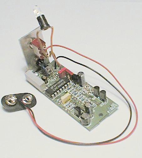 The circuit board has four stages: Amplification of the phototransistor
signal, filtering, thresholding and buffering. These stages are
described below.
The circuit board has four stages: Amplification of the phototransistor
signal, filtering, thresholding and buffering. These stages are
described below.
The phototransistor current connects to an amplifier, designed to give an
output proportional to the percentage change rather than the current
itself. This way the operation becomes independent of the sky brightness.
The second stage of the electronics is an amplifier with a bandpass
filter, that blocks slow variations, as for instance from clouds, as well
as fast variations, from internal noise.
The third stage is a threshold circuit, which outputs a pulse when the
output from the filter stage indicates a sudden drop of light larger
than a certain percentage.
By these three stages, the sensor is matched to objects with the typical
speeds and sizes of C/L models.
The last stage is a buffer capable of driving a long cable that connects
the sensor to a PC.
The unit is powered by a small 9 V battery. An alkaline battery will give
over 100 hours of operation. There is also a battery sensor, sending a
warning if the battery runs low.
Contest Timing
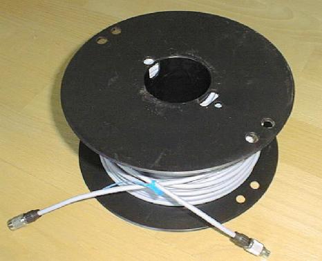 For contest use, the sensor should be placed under the marker for manual
timing. The output signal is then brought through an extension cable,
76 metres long,
(see picture)
to the location of the officials at the opposite side of the circle,
where it is connected to the standard printer port of a PC computer. A
program has been developed that records the times of the sensor pulses,
counts the laps, calculates the speed, as well as the rest of the F2A
flight procedure. There are means to get in synchronism with the manual
timekeepers for the official flight. A hand operated switch also connects
to the PC and is pressed by a timekeeper or handle judge when the pilot
engages his handle to the pylon. The official result as well as the speeds
for all individual laps are displayed and saved to a log file. There are also
means to enter the manual stopwatch times, calculate and register the
result from these. The flight log can later be viewed or printed and handed to the
competitor.
For contest use, the sensor should be placed under the marker for manual
timing. The output signal is then brought through an extension cable,
76 metres long,
(see picture)
to the location of the officials at the opposite side of the circle,
where it is connected to the standard printer port of a PC computer. A
program has been developed that records the times of the sensor pulses,
counts the laps, calculates the speed, as well as the rest of the F2A
flight procedure. There are means to get in synchronism with the manual
timekeepers for the official flight. A hand operated switch also connects
to the PC and is pressed by a timekeeper or handle judge when the pilot
engages his handle to the pylon. The official result as well as the speeds
for all individual laps are displayed and saved to a log file. There are also
means to enter the manual stopwatch times, calculate and register the
result from these. The flight log can later be viewed or printed and handed to the
competitor.
The F2A rules have been amended to detail the use of electronic timing in official capacity.
The program can handle not just F2A but also other categories, which can be defined by the user. There are half a dozen other categories prefefined in the software package, and it is relatively simple to add a category.
PC Computer
Almost any PC or laptop having a PC architecture can be used. There must be a parallel printer port. THE PROGRAM MUST RUN UNDER MSDOS, the old operating system. Windows interrupts the program flow now and then, and this leads to model passes being given the wrong times or missed entirely. For Windows versions later than 98 you will have to prepare a special "MS-DOS boot floppy" to run MS-DOS. However, flight data stored in a log file can be viewed under Windows.An old PC with a 486 CPU running at 33 MHz has an adequate capacity. The screen must be bright enough to be visible outdoors. All computer screens except monochrome LCD will need a shading hood! The internal batterys of old laptops are often worn out, but you want a higher capacity external battery anyway, to get at least six hours of operation.
Accuracy
The PC program reads the sensor signal and registers the time of arrival of the transit pulse leading edge, using the standard internal timebase of the PC. The reading rate depends on the speed of the computer. A laptop with a 266 MHz Pentium gives a 42 microseconds time between readings, and a very old one, with a 8 MHz 8088 (slowest PC there ever was), gives a 3 milliseconds interval, which is too long to work. The worst-case timing error due to the limited sampling rate equals this sampling interval. The time readings are taken from a standard item in PC:s, a quartz crystal controlled timer. In normal operation this is used for timing with a resolution of around 0.055 s. Here it is reconfigured to give a resolution of 838 nanoseconds. The error of this clock is less than 1 in 10000 in all the PC:s I have checked. This error can be reduced by calibration, with a correction entered into the software.The program is able to correct for a missed lap (due to underflying) inside the laps 0 to 9. It also handles sorting out of stray pulses due to, for instance, birds, butterflies or (heaven forbid) R/C models passing.
To measure the timing errors of the sensor itself, an even more accurate
system must be at hand, and none is. Instead, some reasoning could be
done: For F2A models flying at 80 m/s with a fuselage length of 0.4 m, it
takes 4.8 ms from it enters the field of view until it is entirely
visible. Somewhere in this interval the sensor output pulse is produced,
meaning that the difference in time between the actual entry and signal
output can hardly become bigger than this. As the speed is determined by
the difference of two measurements, most timing errors will cancel. Any
net timing error is due to differing conditions for the start and stop
registrations, which could be due to flying height differences and
lighting changes. It is a fair assumption that the timing error is
well below 1 ms.
At the 2004 World Championships, where two independent systems
were used, the time difference was typically less than four units in the
fourth decimal, that is 400 microseconds.
Most of the mentioned errors do not accumulate lap by lap, but have the same value for the total of 9 laps as for one lap. The exception is the PC crystal controlled timer error, and this contributes an error well below 1 ms in 12 seconds, especially if calibrated.
Knowing that the separations of the stopwatch times of good manual timekeepers can be 0.03 seconds, and that sometimes they are much more, we can project this system to be 20 - 100 times more accurate!
The indicated timekeeper uncertainty of 0.03 s corresponds to 0.75 km/h at 300 km/h. As the separation of places at championship events is typically less than that, it is obvious that manual timekeeping is inadequate.
For contest use, there must be a few extra rules agreed upon, using the Sporting Code provision for "local rules". The helpers must not walk in front of the sensor, and so on. The handling of missed laps when they happen for lap 0 or 9 must also be defined. Either use the manual backup, or calculate the speed for laps 1-9 or 0-8, or, more radically, simply cancel the flight. After all, the manual timekeepers will also have a visibility problem if the model passes the timing marker at a height below 0.6 m! (Note that the rules prescribe cancellation of the flight if flying below 1 m for a whole lap.)
Development
The design, prototype construction and testing were all done in the period April - June 2000.First test was on May 1st, with sensor alone, no PC connected, just a light emitting diode to indicate the output signal. It worked right away for F2C models. First test on F2A models with a PC connected was two weeks later, and the second in the Limfjords World Cup competition in Aalborg, Denmark, June 9-10. Then it was tested at the World Championships in Landres, where lots of flight data was recorded.
A printed circuit board was designed already then, and drawings for a box. I gave this to a few sheet metal companies, and got a decent offer from one leading to an order. Then nothing happened, the company was too busy with bigger jobs! Only after actually ordering from two more sources, after ~6 more requests, I finally got the boxes made, in the spring of 2004!
Background
The problem of timing C/L models optically has been on my mind for a decade, at least. Some work on this idea was done in 1997, with the study of stopwatch data from the F2A event at the 1996 W/Ch in Sweden. This led to a Swedish rule proposal redefining the handling of stopwatch readings as well as a provision for the kind of electronic system described here. This rule was approved at the 1998 CIAM plenary meeting. From 2005 the rules have been further amended to clarify the use of electronic timing in official capacity.I'm indebted to Pete Soule for providing the design idea to get rid of the lens and the array of phototransistors I had in mind, and use just a single phototransistor and a slit.
Göran Olsson